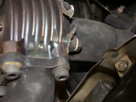

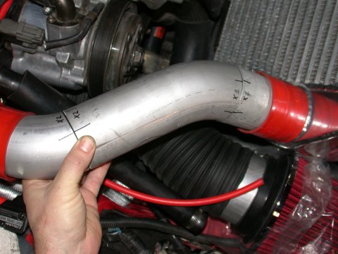
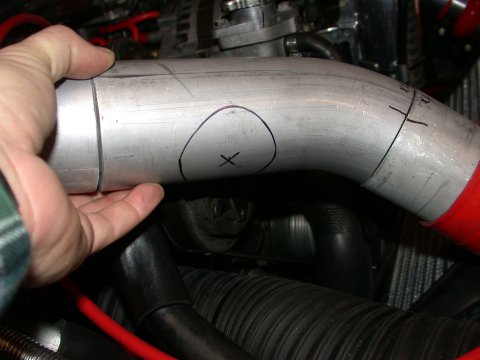
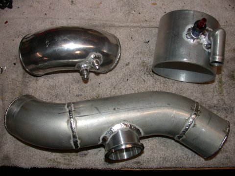
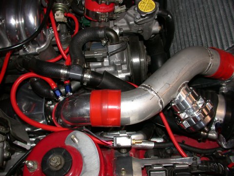
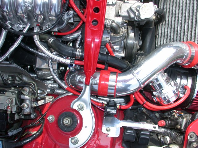
Now particular attention must be paid to the clearance between the compressor outlet elbow and the strut tower bar. Depending on how you have clocked the compressor housing this may or may not be an issue but since mine it clocked so the discharge is essentially pointed vertically (to accomodate the airpump discharge pipe), as suspected the cast 90deg elbow hit the strut bar bracket. Nothing significant but over time the strut tower bar could potentially wear a hole in the pipe and also make a nasty vibration noise during operation. So with some judicious grinding of the offending underside portion of the strut tower bar, cutting about 1/4" off the elbow pipe to lower it, and adding some custom fabricated spacers to the strut tower bar mounting locations I was able to generate about 1/4" to 3/8" clearance between the elbow and the strut tower bar.
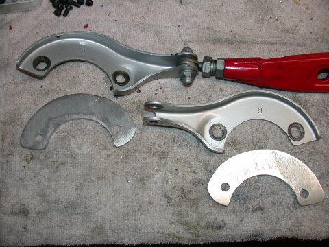
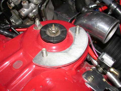
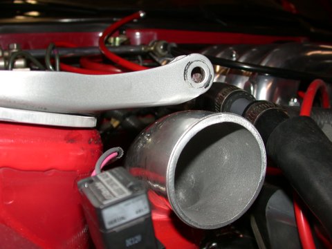
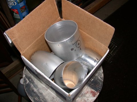
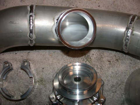
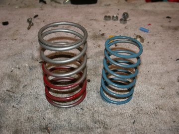
So with parts and raw materials in hand off to Mitch Piper of Piper Motorsports I went. The result is I had a complete “kit” and could finish up with the install. So with the pipes completed I could hook up all the various vacuum lines listed above. The TiAL 50mm BOV is installed on the IC pipe as instructed using the O-ring and V-band flange. Be very careful not to pinch the O-ring during the install. Of note, however, is that the spring that came with the BOV, as purchased, is too heavy for use on a rotary engine that has such low normal engine vacuum (relative to a piston engine). I returned the spring to TiAL and they replaced it “no-charge” other than a $5 shipping cost. The BOV I purchased came with the standard 11lb spring (liftoff at 26inHg which is too high for a rotary). I replaced it with the softest spring TiAL offers - 7lb (liftoff at 18inHg).

The last big obstacle, and it's a big one for most of us, is what to do about tuning. Both for the PFC and the boost controller. The boost controller should be fairly straightforward but the PFC... Switching to a single turbo is going to take you far from the tuning you once had with the old twin turbo setup. And then there is the consideration of other components of your setup. For example, what size injectors used, what size IC, what kind of exhaust system is installed, MP or high flow cat, etc. All these and more will play a role. Lucky for me another friend of mine has travelled much the same road as I have. We share the same size injectors, have stock unported engines, use large/race sized stock mounted IC’s, have 3" full flow exhaust systems, and most importantly bought identical turbo kits from A-Spec. In short, since we had been conversing for well over a year about the conversions we both undertook he was kind enough to share with me his maps for the PFC to get me started. His car has been tuned on a dyno and from here is where I began. A few keystrokes on the Datalogit and with the new tuning installed I will test drive, with a local tuning buddy, logging data from my wideband as I explored the fuel maps.....

There were some items in the "kit" that although may be acceptable, I found it necesssary to
upgrade from what was supplied. Installing a single turbo will cost a lot more than just the “kit!” Note
that some of these items were bought in quantities more than what is needed but at least in my case I was able
to split the cost and product with a friend who was installing his kit at the same time I was. I shall start
with the kit:
![]() GT35R single Turbo kit - A-Spec
to which one might add:
GT35R single Turbo kit - A-Spec
to which one might add:
![]() 1) TiAL 50mm Blow Off Valve w/Aluminum flange, Silver - [new]
(eBay - fasterthanthem.com) $218.00 shipped
1) TiAL 50mm Blow Off Valve w/Aluminum flange, Silver - [new]
(eBay - fasterthanthem.com) $218.00 shipped
![]() 2)Thermo-Tec Heat shielding all from
SpeedZone24-7.com (the “kit” only came with one small 12" square of
adhesive backed Al sheet)
2)Thermo-Tec Heat shielding all from
SpeedZone24-7.com (the “kit” only came with one small 12" square of
adhesive backed Al sheet)
![]() - Heat Barrier FIber Reinforced Adhesive Back aluminum sheets (12" x 24") [pn 13575] (2 boxes)
$32.70
- Heat Barrier FIber Reinforced Adhesive Back aluminum sheets (12" x 24") [pn 13575] (2 boxes)
$32.70
![]() - Thermo-Flex Aluminum cool tube (5/8" x 36") [pn 17062] (2 boxes) $21.38 - small wiring harnesses and turbo coolant hoses
small wiring harnesses and turbo coolant hoses
- Thermo-Flex Aluminum cool tube (5/8" x 36") [pn 17062] (2 boxes) $21.38 - small wiring harnesses and turbo coolant hoses
small wiring harnesses and turbo coolant hoses
![]() - Thermo-Flex Aluminum cool tube (1" x “36") [pn 17100] (2 boxes)
$29.50 - heater hose and AC hard line
- Thermo-Flex Aluminum cool tube (1" x “36") [pn 17100] (2 boxes)
$29.50 - heater hose and AC hard line
![]() - Thermo-Sleeve (5/8" x 36") [pn 14010] (1 box) $13.32 - various
heater hose and larger wiring harnesses
- Thermo-Sleeve (5/8" x 36") [pn 14010] (1 box) $13.32 - various
heater hose and larger wiring harnesses
![]() - Thermo-Sleeve (1/4" to ½" x 36") [pn 14005] (2 boxes) $20.04 -
vacuum lines
- Thermo-Sleeve (1/4" to ½" x 36") [pn 14005] (2 boxes) $20.04 -
vacuum lines
![]() 3) Turbo turbine discharge to DP gasket (1) (pn GRT-GSK-003)
(ATP Turbo) $8.95
3) Turbo turbine discharge to DP gasket (1) (pn GRT-GSK-003)
(ATP Turbo) $8.95
![]() 4) Oil feed line restrictor w/0.035" inlet hole (pn ATP-OIL-021)
(ATP Turbo) $12.00
4) Oil feed line restrictor w/0.035" inlet hole (pn ATP-OIL-021)
(ATP Turbo) $12.00
![]() 5) Turbo compressor discharge 2.5" to 2.75" silicone reducer (1)
(pn ATP-SIL-057) (ATP Turbo) $17.50
5) Turbo compressor discharge 2.5" to 2.75" silicone reducer (1)
(pn ATP-SIL-057) (ATP Turbo) $17.50
![]() 6) IC pipe silicone connector 2.75" straight (1) (pn ATP-SIL-042)
(ATP Turbo) $6.00
6) IC pipe silicone connector 2.75" straight (1) (pn ATP-SIL-042)
(ATP Turbo) $6.00
![]() 7) IC pipe silicone hump connectors 2.75" (2) (pn ATP-SIL-049)
(ATP Turbo) $24.00
7) IC pipe silicone hump connectors 2.75" (2) (pn ATP-SIL-049)
(ATP Turbo) $24.00
![]() 8) T-bar clamp 2.5" for compressor discharge (1) SS Breeze clamp:
$2.37 from PartsSystems.com
8) T-bar clamp 2.5" for compressor discharge (1) SS Breeze clamp:
$2.37 from PartsSystems.com
![]() 9) T-bar clamp 2.75" for compressor to IC piping (1) SS Breeze clamp
$2.40 from PartsSystems.com
9) T-bar clamp 2.75" for compressor to IC piping (1) SS Breeze clamp
$2.40 from PartsSystems.com
![]() 10) -4 AN aluminum weld on vacuum line bungs [I used XRP 6061-T6 fittings]
(3) $15.00 from Livermore Performance
10) -4 AN aluminum weld on vacuum line bungs [I used XRP 6061-T6 fittings]
(3) $15.00 from Livermore Performance
![]() 11) -4 AN vacuum line hose barb fittings [I used XRP Hose End, Push -On,
Straight -4 AN Female fittings] (3) $10.00 from Livermore Performance
11) -4 AN vacuum line hose barb fittings [I used XRP Hose End, Push -On,
Straight -4 AN Female fittings] (3) $10.00 from Livermore Performance
![]() 12) 4" flexible intake hose (pn 53145 K67) [Santoprene: General purpose
polypro/rubber duct hose,
Black 4" ID 4-9/32" OD, 5' length (McMaster-Carr) $23.35 This was split with
a friend - my expense $17.00
12) 4" flexible intake hose (pn 53145 K67) [Santoprene: General purpose
polypro/rubber duct hose,
Black 4" ID 4-9/32" OD, 5' length (McMaster-Carr) $23.35 This was split with
a friend - my expense $17.00
![]() 13) 4" worm gear clamps for intake hose (3) (Home Depot) $5.00
13) 4" worm gear clamps for intake hose (3) (Home Depot) $5.00
![]() 14) Tube of antiseize $3.00 (Pep Boys)
14) Tube of antiseize $3.00 (Pep Boys)
![]() 15) GReddy Profec B Type II Boost controller [new] (eBay) $285.00 shipped from
www.focusparts.com [focusparts.com domian name has since expired so I don't know who these folks are now - search eBay]
15) GReddy Profec B Type II Boost controller [new] (eBay) $285.00 shipped from
www.focusparts.com [focusparts.com domian name has since expired so I don't know who these folks are now - search eBay]
![]() 16) Bag of small zip ties $2.00 (Home Depot)
16) Bag of small zip ties $2.00 (Home Depot)
![]() 17) Proper spec turbo coolant line and oil drain lines. Parker Push-Lok oil
line hose 2' and Parker Push-Lok 3/8" x 3' coolant hose $11.54. These were sourced locally.
17) Proper spec turbo coolant line and oil drain lines. Parker Push-Lok oil
line hose 2' and Parker Push-Lok 3/8" x 3' coolant hose $11.54. These were sourced locally.
![]() 18) Hardware - 5/16" internal tooth star lock washers for wastegate flange
fasteners $2.00 (NAPA autoparts)
18) Hardware - 5/16" internal tooth star lock washers for wastegate flange
fasteners $2.00 (NAPA autoparts)
![]() 19) Hardware - SS shouldered nuts for turbo to manifold connection.
(kit supplied with jam nuts) 4x $1.50 ea: total $6.00 McMaster-Carr (P/N 93776A471) [18-8 Stainless Steel Hex
Serrated-Flange Nut, 3/8"-24 Screw Size, 9/16" W, 11/32" O'All Height]
19) Hardware - SS shouldered nuts for turbo to manifold connection.
(kit supplied with jam nuts) 4x $1.50 ea: total $6.00 McMaster-Carr (P/N 93776A471) [18-8 Stainless Steel Hex
Serrated-Flange Nut, 3/8"-24 Screw Size, 9/16" W, 11/32" O'All Height]
![]() 20) 4" aluminum tube for filter to intake tube connection
(onlinemetals.com) 4" x 0.125" x 3.75" x 12" (12" minimum order)
$15.00 ($10 shipping) This was split with a friend. You will only need about 4"
20) 4" aluminum tube for filter to intake tube connection
(onlinemetals.com) 4" x 0.125" x 3.75" x 12" (12" minimum order)
$15.00 ($10 shipping) This was split with a friend. You will only need about 4"
![]() 21) 2.75" T6061 aluminum tube 90deg elbow
(Burns Stainless) 6" x 12", [pn LB-275-40-16-6061] $75.11
21) 2.75" T6061 aluminum tube 90deg elbow
(Burns Stainless) 6" x 12", [pn LB-275-40-16-6061] $75.11
![]() 22) GReddy 90 deg cast elbow for compressor discharge. This was actually
given to me and as far as I know was part of a GReddy 2 piece IC
hard pipe kit. The GReddy kit goes for about $185. But the piece in question is essentially a tight radius bend 2.75"
diameter
*cast* AL elbow or something like this from EIP tuning (although this is only a 2.5")
elbow image 1
or here elbow image 2
22) GReddy 90 deg cast elbow for compressor discharge. This was actually
given to me and as far as I know was part of a GReddy 2 piece IC
hard pipe kit. The GReddy kit goes for about $185. But the piece in question is essentially a tight radius bend 2.75"
diameter
*cast* AL elbow or something like this from EIP tuning (although this is only a 2.5")
elbow image 1
or here elbow image 2
![]() 22) 6 mm vacuum line (15ft) (
Hose Techniques) $29.25
22) 6 mm vacuum line (15ft) (
Hose Techniques) $29.25
![]() 23) Exhaust manifold to block gaskets -
Racing Beat (pn 16302, ENG-TO-HEAD GASKET 74-75 ALL) (Mazda Pn1757-13-889B) (2) $8.00
23) Exhaust manifold to block gaskets -
Racing Beat (pn 16302, ENG-TO-HEAD GASKET 74-75 ALL) (Mazda Pn1757-13-889B) (2) $8.00
![]() 24) Pack of small vacuum caps for unused vacuum nipples $2.50 (Pep Boys)
24) Pack of small vacuum caps for unused vacuum nipples $2.50 (Pep Boys)
Shipping costs for all these bits and pieces. Est. $75.00
And some of the extras I purchased for my install:
![]() 25) Brass fittings for Oil pan vent line $6.00
25) Brass fittings for Oil pan vent line $6.00
![]() 26) Air pump 3/4" vent line “T” $1.00
26) Air pump 3/4" vent line “T” $1.00
And don’t forget to add to this the cost of having new IC and intake piping fabricated. $90.00
So if you want to be honest with yourself, installing one of these kits **YOURSELF** will cost you probably over
$1000.00 more than the price of just the kit itself depending on the quality of the parts you purchase
and what you had previously installed on your car. Note, however, that about $500 of this additional cost
was for the BOV and the Profec B boost controller.
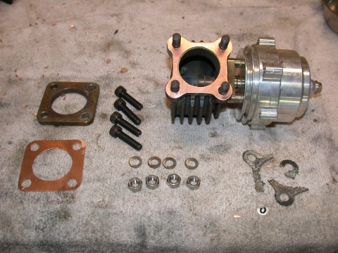
Day 1 went fine. And then there was day 2 when the excitment started. First session of the day started fine so I decided to flip on the controller and try 12psi of boost. Well things weren't all roses and some nasty sounds began eminating from the exhaust system and boost begin to wane shortly thereafter. Turns out the wastegate inlet flange connection had shed two of the retailing bolts (simply gone) and the other two were rattling around in their holes they were so loose, resulting in the metal/fiber gasket being completely blown out. Two hours under the car during the lunch break and I managed to find replacement hardware, reused the other gasket from the exhaust side of the wastegate, and hit the track again. BAH! Same problem. The hardware and gaskets just didn't seem up to the task. I return home and with the help of some friends, all with the same GT35R kit and all experiencing the same problem on the track, there are 3 of us, we agreed that copper gaskets and some fancy new locking hardware, the flanged connection would stand some chance of holding up the heat of a hardworking wastegate at track temperatures. I replaced the bolts with a stud and nut arrangement and used a great SS locking washer called Nordlocks. The copper gaskets were hand cut from 0.025" thick copper sheet. I replaced both the inlet and discharge gaskets. The hardware was longer (30mm vs. the supplied 25mm) SHCS on the inlet side (8.8grade - M8x30mm) and studs and SS nuts on the discharge side. (8.8grade - M8x25)(SS M8 nuts) All mounted using Nordlock washers (NL8mm SS) The hardware was all bought from MDMetric.com See pictures below. The result was that at the next track weekend I successfully ran 12psi all weekend with no wastegate issues to speak of and all the hardware remained tight.
