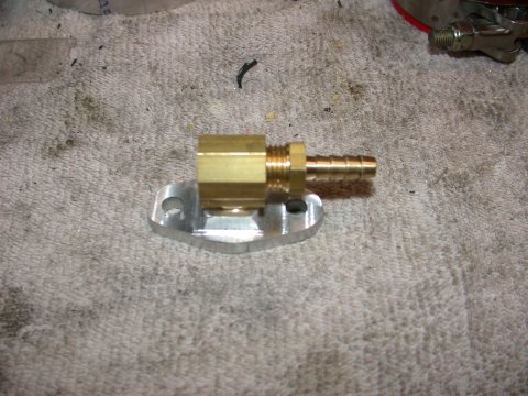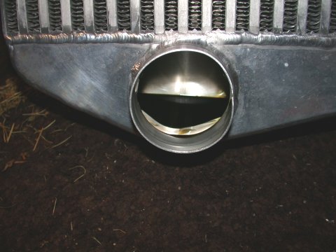

Perhaps one of the single biggest fears I had about going to a single turbo setup is that installation of the new parts would require removal of, or rendering inoperable, the emissions control components needed to pass emissions testing in my state (MD). Part of the reason I went with the A-Spec kit was the potential to retain use of the OE mechanical air-pump. Other options were available, like using a GM electric air-pump from either a Corvette or Camaro. More work involved and purportedly they have a tendency to burn up rather quickly when used on an RX-7. So after fitting the turbo and plumbing, the first thing I wanted to tackle was refitting the OE air-pump. Well whattaya know! It fits perfectly with no interference with the turbo itself. One catch however. It may clear the turbo but the lower mounting bracket on the air-pump sits right in the path of the inlet hose to the turbo. Not a problem. Out comes the hack saw and off it comes...no more interference problem.
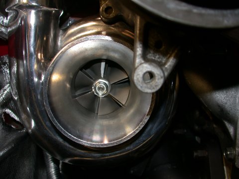
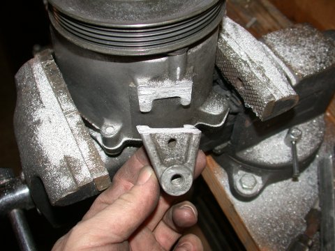
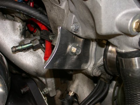
With the lower bracket now gone the question is now how to support the air-pump. Chuck Westbrook (CEWRX7 on the RX-7 club forum) was kind enough to develop a support bracket that can be made easily with a metal saw, a file, and drill. I used 3/8" AL plate. Took me an hour. So now I have a working functional air-pump. Although not bolted on the lower end, the upper bracket combined with the belt tension is enough to keep the airpump well and truely seated in the bracket. Maintaining the OEM airpump means I can keep the air control valve (ACV) and associated plumbing. This is good for emissions
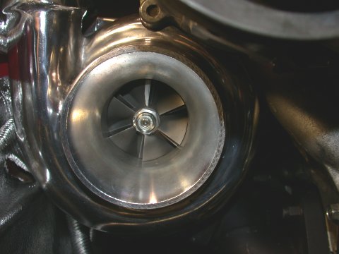
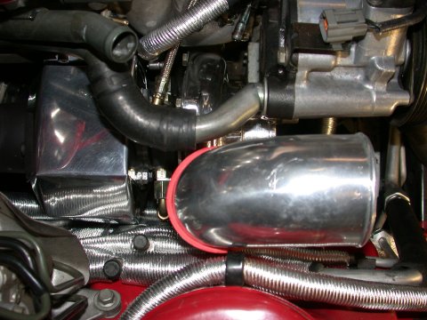
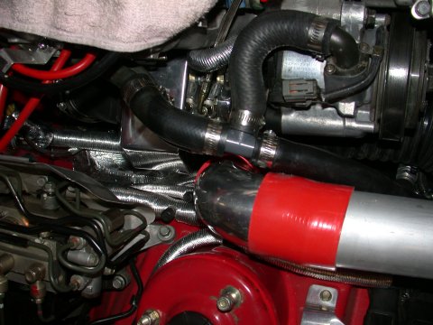
To feed the airpump I removed the inlet elbow and flipped it around and reused my old airpump and pressure relief valve hose with a “T” from a local hardware store and it should tap into the intake just like my old CWR intake did. The airpump outlet is reconnected as it was using the original hose. Before assembling all the air-pump hardware however I did cut to length the 4" flexible turbo inlet tubing (bought from McMaster-Carr: see page 4 for details and specs. Link below) and clamped it to the turbo compressor as it’s kind of hard to get to with the air-pump in place. When all is said and done I shouldn't have any problems with passing emissions or visual inspection.
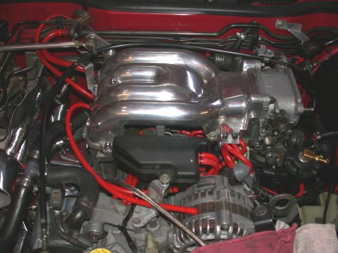

First up and possibly the hardest part was removing the vacuum tank buried under the alternator and power steering bracket. You guessed it. Alternator must be disconnected and removed and the black tensioner bracket loosened to facilitate prying the pressure tank out of it’s hole. The vacuum tank has only two 10mm bolts (top and bottom). I removed the lower end of the alternator tensioner/adjustment bracket (it’s a water pump bolt) and simply loosened the upper bolt and it rotated out of the way. The engine lift bracket must also be removed (2 12mm bolts) Not so fast. Still not enough room. The coil pack was in the way. This means the oil filler neck is removed, coil pack is unplugged and spark plug wires disconnected and the coil pack is removed (4 10mm nuts). Under the coil pack are the three 12mm nuts to unbolt the solenoid rack. All this to remove the pressure tank? With coil pack out of the way, the solenoid rack loose, and the alternator tensioner/adjustment bracket rotated out of the way there is enough room to wiggle the vacuum tank out. Super.
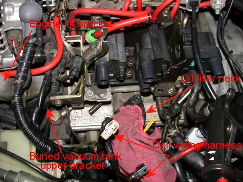
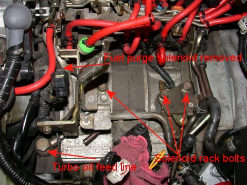


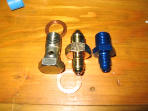
| With the pressure tank out of the way there is now clear access to the other end of the oil feed line for the turbo. Unbolt the oil line banjo bolt and wiggle out the double hard line. Using the supplied banjo bolt fitting for the SS turbo oilfeed line, route the SS line in a location that would run behind the alternator once it’s installed and install the fitting and line. I had to temporarily disconnect a few electrical connectors on the back of the water pump housing to route the oil line. With the new oil feed line installed, the engine lift bracket, alternator bracket, and alternator can be reinstalled. Note, apparently my kit was supplied with a banjo bolt adapter while others have received an adapter fitting in lieu of what I received. There have been reported issues with the other supplied adapter, i.e. a metric to AN adapter with a flared metric end. |
 |
|---|


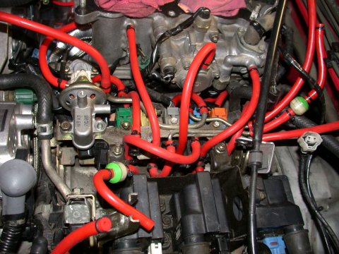

Other items that can be removed are the vacuum reservoir, (D) the EGR control solenoid and the EGR valve itself which can no longer be mounted and is therefore useless and (G) double throttle control solenoid. Due to ignorance at the time I have not removed the EGR hardware and double throttle control hardware but may go back and remove these at a later date to further simplify the overall system. With these hoses and solenoids removed it is plain to see that most if not all of the metal solenoid rack “spider” (spaghetti of metal tubes) are now unused. The rack spider is composed of several parts screwed together. Depending on how you feel you can either remove the solenoid rack entirely and let the remaining solenoids hang freely or you can leave the rack in place and simply remove the spider from the top of the rack. I chose the latter. Also with many solenoids removed there remains the electrical connectors and harness. Some have cut off the connectors but since I hate doing anything I can't easily reverse I simply taped them up well and tucked the connectors away. If you are using an Apexi Power FC for engine management no in-line resistors are needed in the connectors. The Power FC simply ignores the unused connectors and will therefore not trigger any engine fault codes due to their absence.
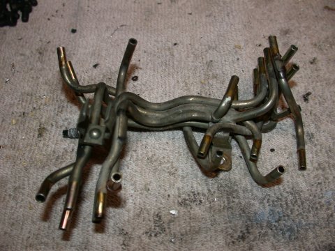
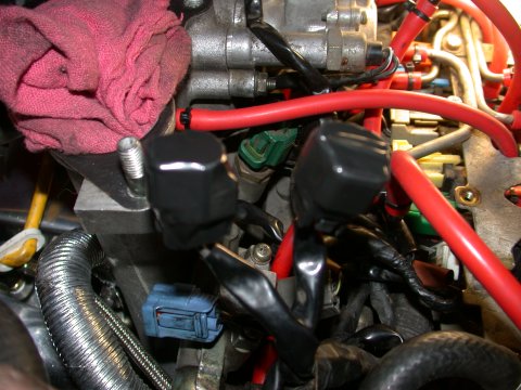
So after all is said and done all that should remain [for an emissions compliant vehicle] is the (A) fuel pressure regulator solenoid, (B) and (C) the two airbypass solenoids (for the ACV - to get me through emissions), and the (K) fuel purge control solenoid. [and in my case (D) EGR and (G) double throttle control solenoids] Wow. Not a whole lot left eh? With all unnecessary components removed reinstall the rack, ignition coils, electrical connectors and spark plug wires, oil filler neck, and eventually the UIM.

ADDENDUM: After living iwth the temporary
zip tie mount I came to end of my rope and decided I had to put it somewhere. Reluctantly the only accessable and
visible place I felt I could put it was in one of the radio DIN slots. This was going to pose a problem as I had the
factory tuner/CD player head units taking up both slots. [wink wink] Guess I'll just have to buy a new radio! This is
how the downward modification spiral begins BTW. And so it was the old trusty OEM radio and CD player were removed
and in it's place was installed an Alpine CDA-9853 CD player stereo Headunit. A pretty trick piece with a detachable
flip face mechanism to allow loading of CD's. My only disappointment is that the colors don't match the rest of the interior
when backlit. To install the head unit I fabricated a wiring harness to the OEM plugs using a Metra harness (pn:70-7901 Mazda 1990-2001).
sourced from Best Buys and an antenna splitter (Antennaworks pn:40-UV42) sourced from Crutchfield. So that took care of
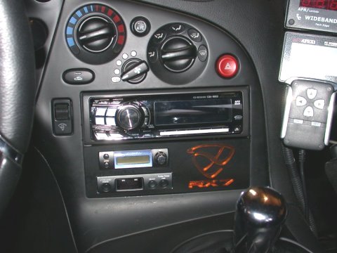
the audio. Now for the real issue, how to mount the Profec B boost controller. A fine gent on the RX7 club forum began
laser cutting neat little DIN panels with inlaid RX-7 rotary insignia...and he would cut holes to each customers request.
And so it was I came to buy the DIN panel that would accommodate my Profec B and my old GReddy turbo timer. Lucky me.
A bit of double sided tape and all fit in very nicely. The holes cut for the two controllers are so snug that no other
mounting hardware is necessary. Maybe some day I will backlight the efini logo...good stuff. See below for picture of the final setup.
The wiring harness from the solenoid is long enough to run the
width of the car, through the firewall on the drivers side main wiring harness firewall pass-through, and up to where I
have the controller mounted with perhaps 12 inches to spare. The controller is powered by tapping the
black and yellow striped wire from the fuse box by the drivers left foot (requires dead pedal removal).
This is a 12v switched power source.
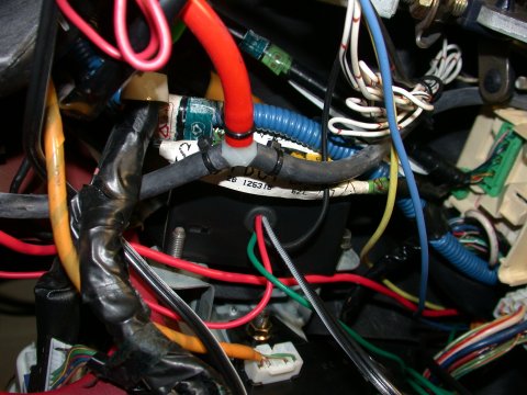

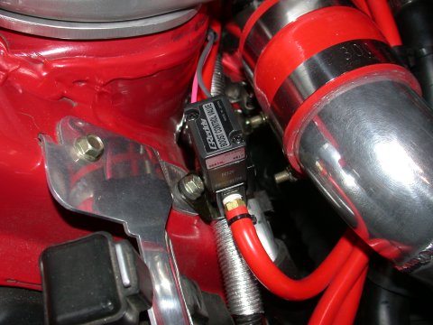
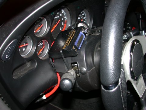
Per page 38 of the GReddy Profec manual, which describes the hookup for external wastegates, I connected vacuum
lines in the following way. The Solenoid contains three ports. I used the COM and NC
ports. From the NC port is routed a 6mm vacuum line to a nipple
on the compressor discharge pipe [12" 6mm] (instruction line item 5) and from the COM port a line is
routed to the top port on the wastegate [3' 6mm] (instruction lines 3 and 4). The side port on the wastegate
is routed to an unused nipple on the front side of the UIM [3' 6mm] (this is per the TiAL wastegate
installation diagram). And the vacuum line run from the boost controller itself is “T”d under the dash to the vacuum
line shared with my analog boost gauge [6" 4mm] (see image above). This shared vacuum source comes from the UIM also -
one of the two outside nipples facing the turbo. I want the ECU and the boost controller to see the same
signal (boost). That way if the engine is seeing 12psi of boost this will correspond directly to the
12psi row on the maps in the PFC. Taking the boost signal for the controller from here rather than the
compressor discharge will do this.
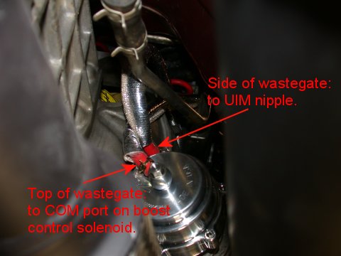

Now there are several other components left to reconnect from the new turbo installation and most of which use 6mm hose. These include the fuel injector atomization pressure line to another nipple on the compressor discharge [18" 6mm] and the oil injector vacuum line to the compressor inlet. This is a nipple welded to a short length of AL pipe attaching the intake filter to the intake tube [3' 6mm]. Additionally vacuum line is run from the UIM to the TiAL BOV mounted to the compressor disharge pipe [2' 6mm]. Below is an overall simplified vacuum hose diagram modified from "xstransam's" that sums up the lines I ran for my single turbo installation. The caveat being the PCV lines that may be deleted if a catch can is being used.

