

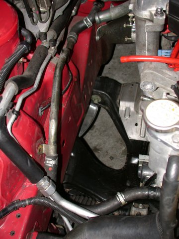
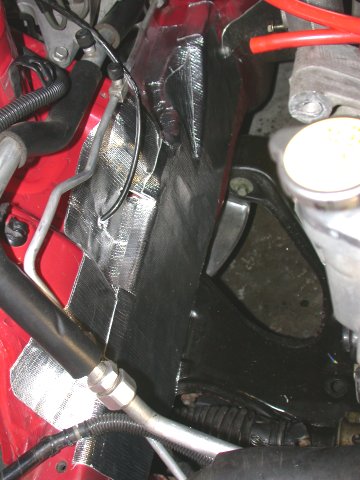
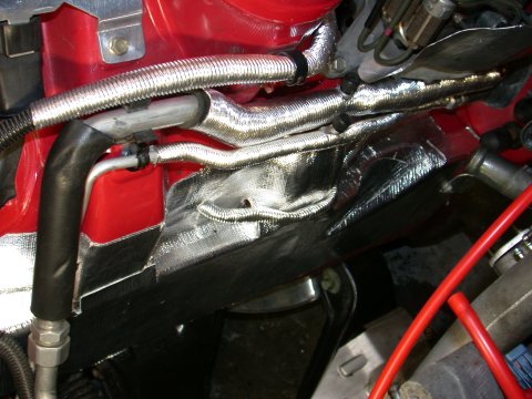
As is typical with fabrications of this sort there is always welding spatter, rough edges, weld buildup where not desirable, etc., so a bit of grinding is in order. I cleaned up some of the flow paths inside the manifold and had to grind a bit of the wastegate flanges to allow the bolt heads to sit flat on the flange. Next was bolt the wastegate to the exhaust manifold. Assemble in this order: manifold, gasket, valve seat, and then wastegate. I used four black 8mm 1.25 pitch cap head screws (supplied with the kit) with serrated star washers (not supplied with the kit) with anti-seize on the bolt threads. The washers keep the bolts locked in place, the antiseize makes their removal easier.
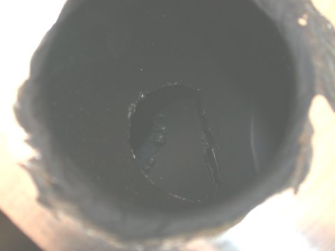
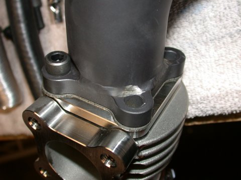
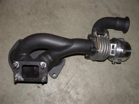
The key is to ensure the wastegate outlet points in the correct orientation, i.e., pointed down when manifold is mounted to the engine (as pictured below). I then bolted the short wastegate dump tube to the wastegate using the supplied gasket and four black 6mm 1.25 pitch cap head screws and serrated star washers and anti-seize. Install the 4 supplied manifold studs in the manifold discharge side (again I used anti-seize). Make sure the studs are in all the way. I had to clean up the threads in two of the manifold holes before installing the studs as they wouldn't seat all the way in. With the manifold ready, bolt it to the engine block. And I’d suggest using new manifold to block gaskets and new nuts for the studs. Torque appropriately. Good. The manifold is now in place. For grins drop on the new turbo stand back and take a gander....for motivation.

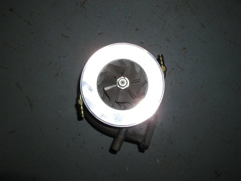
Back to reality. Check the clock position of the turbo compressor and turbine sections to ensure proper rotation of the CHRA (center section rotating assembly). Mine was oriented correctly and only required a small tweak to the compressor housing. However if you do need to spin things, loosen the mounting nuts holding the turbine housing and compressor housing to the CHRA. Use one nut on each, finger tight, to hold the turbo assembly in position. Set the turbo on the manifold. Check that the CHRA oil inlet and outlet ports point vertically up and down and that the compressor discharge is where you want it. Loosen the finger tight bolts accordingly and rotate the CHRA to the desired position. Note it's only the tubrine that bolts to the manifold. Retighten (fingertight) the one turbine and compressor housing bolt(s) after orientation is correct. Remove the turbo from the manifold and re-tighten the remaining bolts housing bolts. Next is to install the fittings on the CHRA. Coolant inlet and outlet 90 degree fittings (supplied with the kit), engine side pointing up, chassis side pointing down. The oil outlet uses the angled adapter with a gasket. I used the two button head screws provided. The oil drain adapter is angled toward the chassis and away from the manifold. For the oil inlet I installed the restrictor [details here] I purchased from ATP Turbo instead of the adapter provided with the kit from A-Spec. Although coolant fittings and the oil inlet fitting are compression fittings I also wrapped the threads with pipe sealant...just in case.

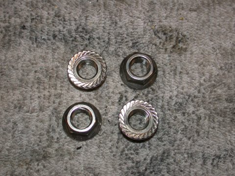
During the course of this exercise I felt it necessary, that although the turbo turbine, manifold, and DP are ceramic coated, to somehow shield the lower intake manifold (LIM) from this extreme heat source. So getting out my trusty tin snips, a piece of sheet aluminum and my 18" mini-bending brake I whipped up a small heat shield/shroud for the turbine and fitted it to the turbo, polished of course. Better than nothing. With the turbo prepped, install it on the manifold, remember to install the manifold to turbo metal gasket. It is somewhat difficult to tighten the turbo to manifold nuts with anything but a box end wrench and neigh on impossible to use a torque wrench. Do the best you can is all I can say. My A-Spec kit unfortunately came supplied with small jam nuts for use on the turbo flanged connection. Passable but far from ideal. They may work fine but most likely would create big issues trying to remove them after several years of use should the turbo need servicing for some reason. A friend was able to source some Stainless Steel serated surface shouldered nuts for this application. Much more appropriate here even if they did cost $1.50 each!

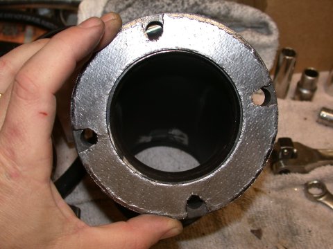
With the turbo now fixed in place, mount the short turbo discharge Down Pipe (DP) stub pipe. Here I used a modified carbon gasket at the flanged interface. In theory the metal to metal face should seal but I’ve know in some cases that it has leaked, so I chose to use the gasket. It isn’t a perfect fit so some trimming with tin snips is necessary. I used the four remaining black 8mm 1.25 pitch cap head screws from the kit but also used some SS flat washers as the holes in the short turbine discharge pipe were too large for the head size on the cap screws. I would have liked to have also used serrated star washers but the added thickness of the gasket and the flat washers in addition to the star washers would have made the bolts too short. I might switch to better (longer) hardware in the future. The jury is still out.
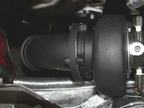
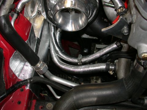
| So with the turbo and exhaust now mounted it was time to tackle the plumbing - high pressure oil feed line, gravity oil drain line, and coolant inlet and outlet lines. First up was to install the short hose for the coolant inlet. But what’s this? The kit was supplied with high pressure fuel line hose for coolant? Dang it! Fuel line hose, although passable is not recommended for use with coolant. A check of the oil drain hose and same problem again. My A-Spec kit was supplied with heater hose. Heater hose is not recommended for use in oil. From an email recieved from the Gates Hose Company, “do not use an EPDM heater hose on a oil application because the hose will have a premature failure. You need a Nitrile hose for an oil application.” So off to the local supplier for the right sized heater hose and larger oil drain hose. I installed the short coolant inlet hose from water pump to turbo, properly sheathed in thermal insulation, then installed the SS oil feed line to the turbo, then crawled under the car and installed the coolant return line from turbo to water pump housing, again sheathed, and then finally the short oil drain line from the underside of the turbo to the forward OE oil drain line fitting. Fully plumbed the turbo was now done. It would of course be nicer to use braided line with An fittings but I will save this for another day. Right now I just wanted to get things installed and sorted, then I can go for the good stuff. |
 |
|---|
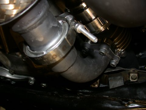
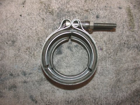
Next up is to mount the DP. Note the Aluminum transmission undertray must be removed and notched before reinstalling in order to clear the wastegate dump tube. First get all the parts in place and loosely lined up. Looslely bolt the DP to the MP, and loosley install the two V-Band clamps (DP and wastegate dump pipe). Tighten in a sequence from turbo to MP. Well not so fast. Trouble is I had a really hard time getting the V-Band clamps to nicely cinch down on the connection and pull the flanges together. The flanges must be perfectly aligned. I ended up using anti-seize on the V-Band surfaces to help them slide a bit better and loosened the DP stub pipe to turbine discharge to make aligning the two DP sections at the V-Band easier.
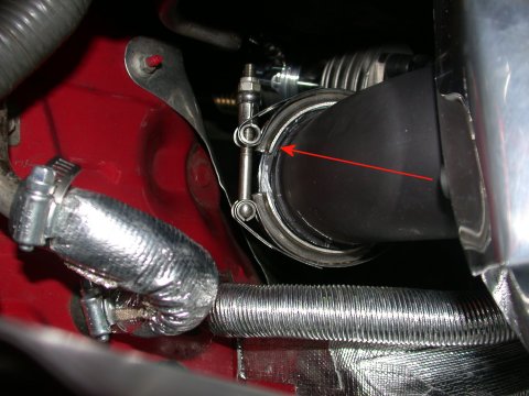
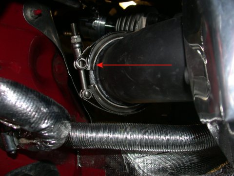
I tightened the DP V-Band from under the car so just in case it leaks the hot exhaust gas will be pointed down and not back up into the engine bay. Then I went back and re-tightened the turbine outlet flange connection, then the DP to MP, and then the wastegate dump tube V-Band. Ugh! Now the wastegate V-Band was giving me issues! So I loosened the dump tube at the wastegate and tightened the V-Band connection first and then went back and snugged down the wastegate flange. Pay particular note to the wastegate V-Band clamp. Initially my A-Spec kit came with a clamp made by R.G. Ray. This 2" clamp was two large and at full closure was still loose on the connection. A-Spec came through and sent me another 2" clamp made by Nelson which was significantly smaller and which fit fine. Overall installing the DP may sounds easy in principle but trying to do it alone I found myself using every elbow, knee, and forehead I had to hold things in place while I tightened each connection.
TRIPLE-R
MAIN PAGE
GENERAL
OVERVIEW | THE
HEART OF THE BEAST | STOPPING
AND TURNING | THE
COMFORT ZONE