

When RC was purchased it was missing two critical components and engine and a differential. The engine has been taken care of and now was time to face the differential. I have to say that in this instance I am the lucky (time will tell) beneficiary of someone else's ingenuity and hard work. A few months go I was lucky enough to stumble upon a differential for sale that I originally was going to use to replace the open differential in Rusty. It cost me the princely sum of $400. WOW! $400! A lot of dinero? Well, this is no ordinary differential. This differential uses the Torsen unit from a Miata. Not only that but the 4.33:1 ring and pinion gears from a rare GTUs FC have also been fitted. The standard ring an pinion drive ratio for a manual transmission equipped car is a 4.1:1. Pricing a 4.33:1 ring and pinion will in itself approach $400 so I considered the whole unit as purchased to be worth the expense. The Torsen Limited Slip Differential (LSD) was purportedly taken from a 94+ 1.8L Miata with 60,000 miles. I've heard it is tricky to know which Miatas were fitted with a Torsen unit but they can be had used for as low as $150.....if you can find them.
This Torsen LSD “modification” can replace any differential for a 86-91 normally aspirated RX-7. First we'll take a look at the 94+ Miata rear end. You will see ten 12mm bolts (Left image below: arrow indicating one of the bolts) circling the outside of the diff. You will start by removing the housing bolts. Once the differential is open, the right image below is what you will be looking at. You will then continue by removing the four 12mm bolts (red arrows) that hold down the bearing guides, as well as the 10mm bolts on the top of them (yellow arrows)
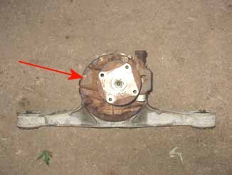
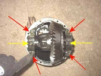
In the beginning there was a Miata differential
After that is removed, the Torsen type LSD and the ring gear will pull right out. This is what you will have.
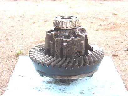
A thing of beauty? A Torsen Differential
Now you will be removing the ring gear from the Torsen type LSD unit. The Miata ring gear is not compatible with the RX7 pinion gear. The ring gear is held on by the ten 14mm bolts on the outer ring of the LSD. You will need an impact gun to remove these, they are on there extraordinarily tight. Once you have unbolted all ten bolts, the ring gear will be able to be removed from the unit. You will most likely need to tap it off with a hammer (gently) as it is a tight fit. Once you have removed the gear, this is what you will be left with.
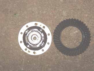
With ring gear removed from the Miata Torsen
Now, you will repeat the process exactly for the FC differential. Once you get the ring gear off of your old FC viscous type LSD, it is time to install it onto the Miata Torsen LSD. Just slide it on, and torque all of the ten 14mm bolts down to the proper spec, and in proper sequence (can be found is FSM). Now you will have your FC ring gear onto the Miata Torsen LSD. Now, its time to re-install the LSD into the FC housing. If your bearing guides and caps have become separated, like this they will need put back together. The bearing guide slides inside of the cap, and the outer holder then threads into the side of the bearing retainer. It should look like this when together.
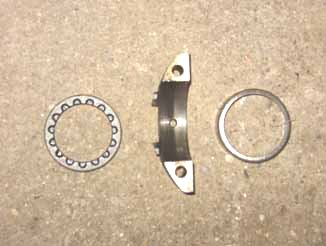
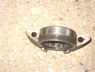
Bearing Guides and Caps shown apart (left) and assembled
(right)
Now that you have the empty FC housing...It’s time to set in the Miata Torsen LSD and the FC ring gear assembly. Set it in place so that the bearing guides line up, with the bearing being inside of the retainer, and you can bolt it down to the proper spec.
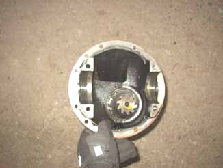
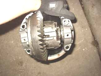
An empty pumpkin (left) and with Torsen fitted to FC
housing (right)
Use a new gasket, or silicone the differential housings, and then reinstall the two pieces of the housings back together, and you are done! Sorta...
Of particular note, however, is that the housing from an S5 LSD uses un-equal length axle stubs. When using and S5 viscous type LSD and stub axles as a starting platform, the longer stub will cross over and cause the replacement Torsen LSD unit to be "fused" together, making it impossible for both wheels to spin at anything other than the same speed. Installation of equal length S4 axle stubs will correct the problem. Additionally, before final assembly, the backlash will need adjusted properly to spec. If not the gears will whine and ultimately destroy the gears It is a fairly simple procedure but it does require a few special tools (dial indicator and something to turn the things on the side of the bearings. Mazda calls for a differential wrench, but anything you can turn them with will be fine) The procedure to set backlash is explained in chapter 9 of the FSM, pages 9.43-9.45.
So there you have it. Next up how to fit this thing into the car. Not very easily I can tell you if you are doing this alone and on the floor of your garage like I did. Keep in mind I'm starting from scratch; no axle, no half-shafts, no camber link, and no differential fitted - this is an installation only. In short the entire rear sub-frame must be lowered about 4-6 inches (just to the end of the studs on the chassis). I had the entire car up on jack stands and a floor jack under each side of the rear sub-frame.
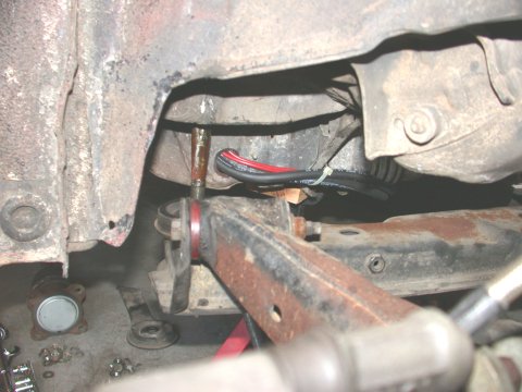
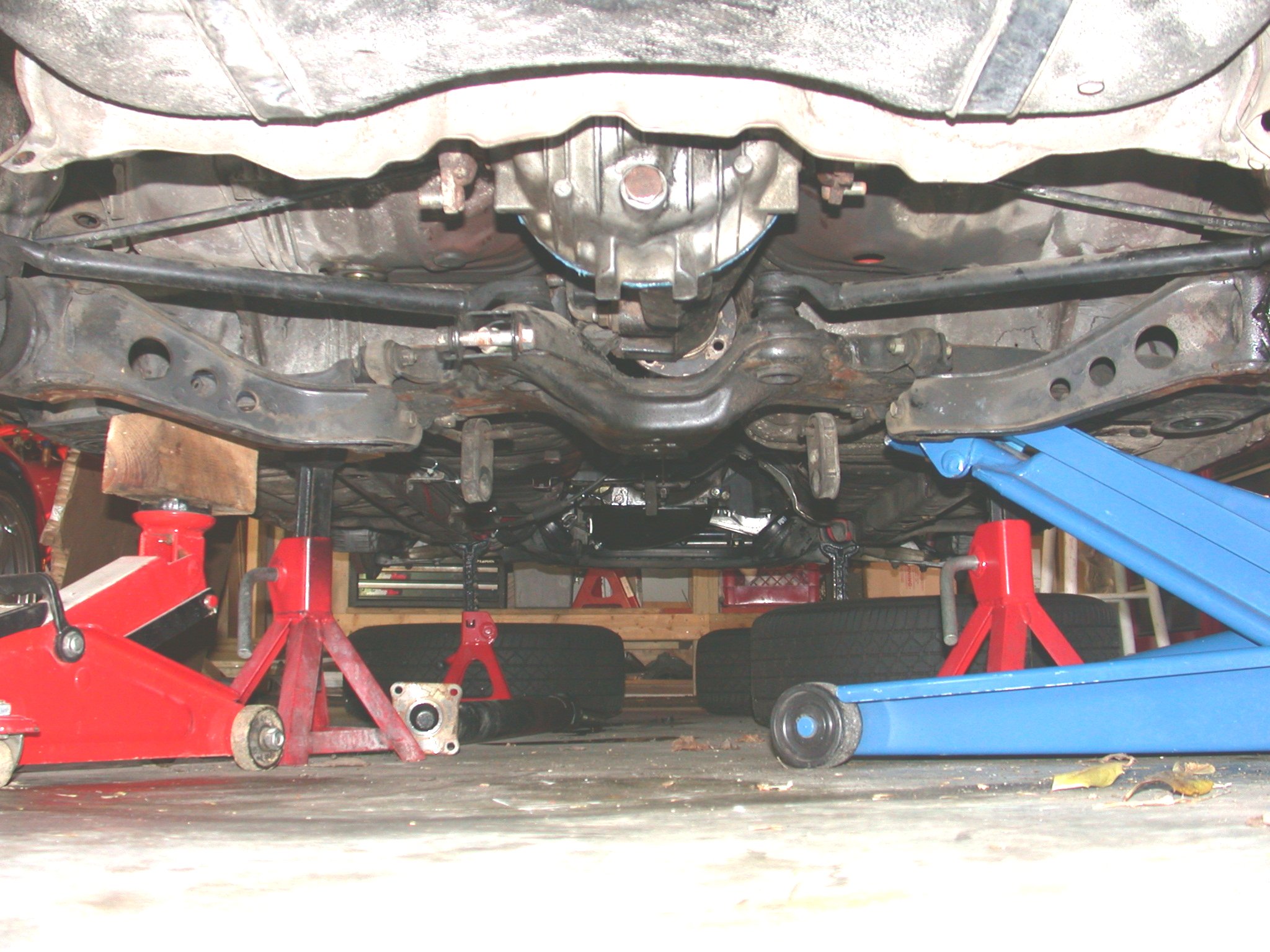
Dropping the sub-frame about 6 inches (left) using two
floor jacks for support (right)
Unbolt the big 17mm nuts fixing the sub-frame to the bottom of the car on either side. Undo the smaller 12mm sub-frame bracket bolt and remove the sub-frame bracket. Then I slowly used the floor jacks to lower the sub-frame to just about the end of the chassis studs. The idea is to drop the sub-frame just low enough such that nose of the differential can be lofted into place and the front differential bushing bolts can be inserted into the slots/cradles in the sub-frame. This is a real PITA. So there you are with 70lbs of differential perched over your noggin after just having bench pressed the pumpkin into place, the front differential bushing is just about in the right place, and the rear arms of the differential have been slid over their respective chassis bushing studs and......now where did I put those chassis bushing plates and bolts? Using an elbow and knees hold differential in place hoping it won't fall on your nose you grab madly for the chassis bushing plates and nuts, call for 6 year old son (insert innocent young child, moronic non mechanically inclined neighbor, clueless best friend, idyllic girlfriend but who doesn't like grease and oil, or couldn't care less about cars spouse but who likes your nose, here) to help you find them, trying hard to see where the stud is while sweat runs into your left eye, place hand blindly on a bushing plate and nut from under left ear (how in the heck did THAT get there?) and as quickly as possible get one or two threads onto each stud before fatigue sets in and you can let go of the differential while 6 year old son runs away crying. Like I said a real PITA.
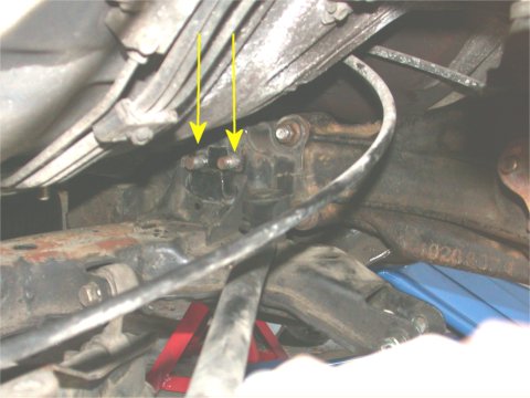
The two problematic front differential bushing mounting
studs.
After consoling 6 year old son (or other...see above) you can return to the car. The real trick then comes when trying to tighten the front differential bushing nuts. There are two of them and they are neigh on impossible to get a tool on. Drop the sub-frame too low and the bushing studs won't seat into their slots in the sub-frame. Have the sub-frame too high and you can't get a wrench in there to tighten the nuts. It's all a compromise. I managed with a ratchet and a few extensions but even then it was only a few clicks at a time when tightening. Next up is too install the axles and drive-shaft. The axles are kinda tricky as this requires removing the lower end of the rear shock from the wheel hub and letting it hang down to just low enough so the axles can be slid into place and the flange at the other end of the shaft can be fitted over the studs on the differential axles stubs. I placed a floor jack under the brake rotor so the weight of the hub is not on the brake line when the hub is dropped, the brake line being pretty much all that keeps the whole hub from dropping to the floor. Installing the drive-shaft is easy so no hints provided here. The FSM will give all the torque specs for these hookups.
7-UP CLUB
MAIN
OUR "LOCAL7"
COMMUNITY | THE
WORLD OF THE RX-7
This page last updated May 3, 2004